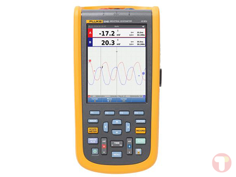
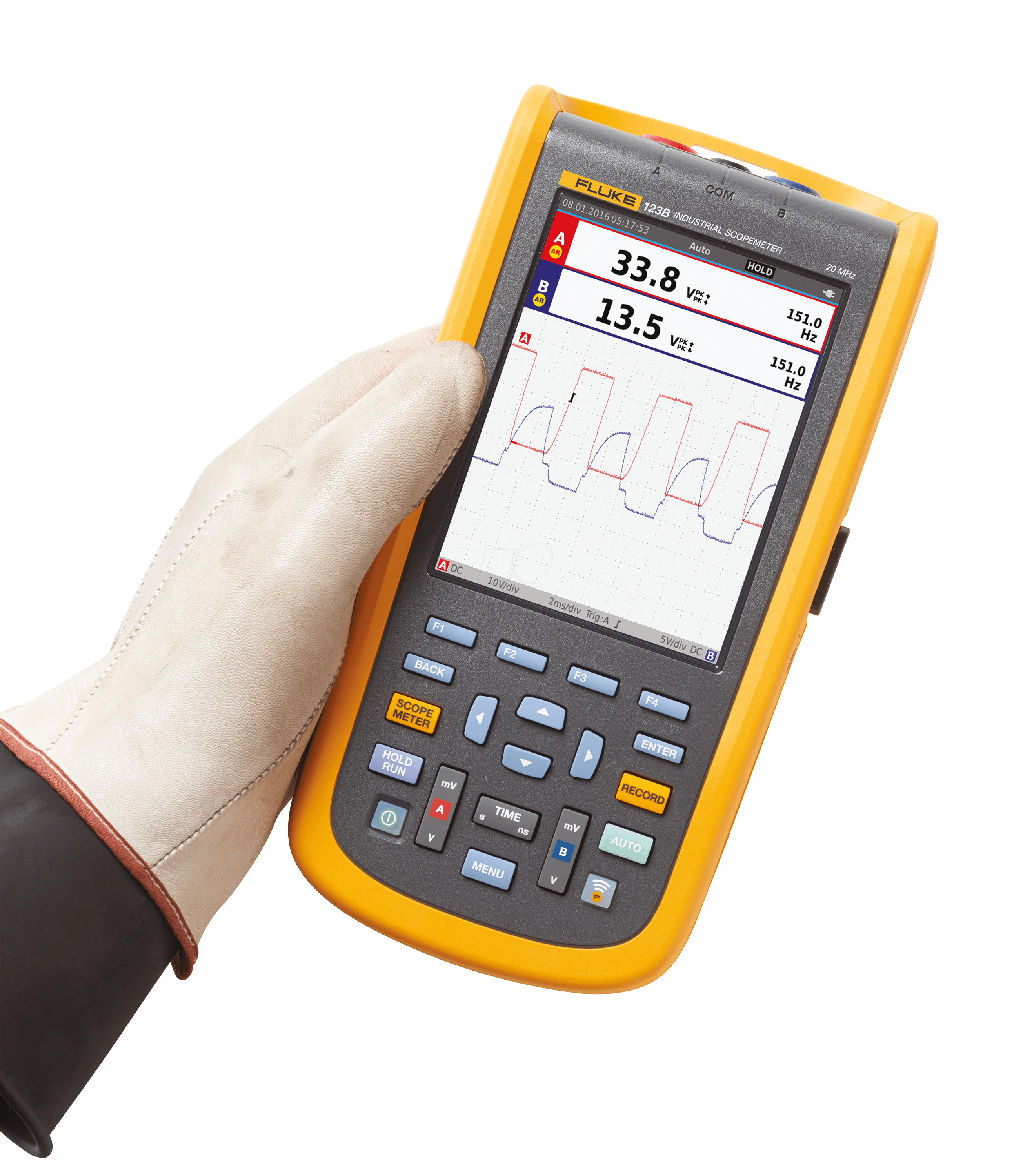
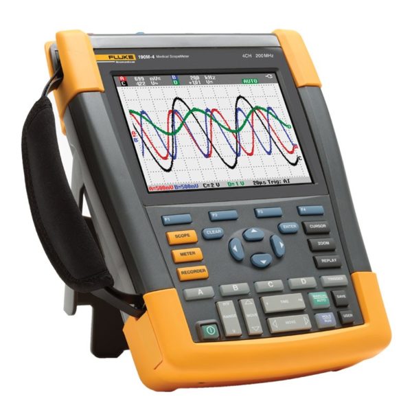
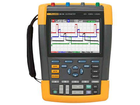
The Fluke 120B Series ScopeMeter oscilloscope is a rugged solution for industrial electrical and electro-mechanical equipment troubleshooting and maintenance applications. It’s a truly integrated test tool, with oscilloscope, multimeter, and high-speed recorder in one easy-to-use instrument. The ScopeMeter 120B Series also integrates with Fluke Connect mobile app and FlukeView software to enable further collaboration, data analysis, and archiving of critical test information.
The 120B series includes innovative functions designed to help technicians troubleshoot faster and get the answers they need to keep their systems up and running. Display waveforms with Connect and View™ trigger and setup technology and automatically view related numerical measurements using Fluke IntellaSet technology, all without making manual measurement adjustments. With Recorder Event Detect capabilities, elusive intermittent events are captured and logged for easy viewing and analysis.
The Fluke 120B series is available in three models:
- The 123B is a full function dual input scope and meter with 20MHz bandwidth and recorder function.
- The 124B is a full function dual input scope and meter with 40MHz bandwidth and recorder function capable of scope cursor measurements. A 10:1 voltage probe is also included.
- The 125B is a full function dual input scope and meter with 40MHz bandwidth and recorder function capable of scope cursor measurements. The 125B also includes advanced power and harmonics measurements as well as bus health analytics. A 10:1 voltage probe and i400S current clamp are also included.
Connect-and-View™ triggering for an instant, stable display
Oscilloscope users know how difficult triggering can be. Using the wrong settings can lead to unstable waveform captures, and sometimes the wrong measurement data. This instrument’s unique Connect-andView™ triggering technology recognizes signal patterns, and automatically sets up the correct triggering to provide a stable, reliable and repeatable display. Connect-and-View™ triggering is designed to work with virtually any signal, including motor drives and control signals – without adjusting parameters, or even touching a button. Signal changes are instantly recognized and settings are automatically adjusted, providing a stable display even when measuring multiple test points in quick succession.
IntellaSet™/AutoReading
The Auto Readings function with Fluke IntellaSet™ technology uses proprietary algorithms to intelligently analyze the measured waveform and automatically displays the most appropriate numerical measurements on screen, so you can get the data you need easier than ever before. As an example, when the measured waveform is a line voltage signal, the Vrms and Hz readings are automatically displayed, whereas if the measured waveform is a square wave, the peak-peak and Hz readings are automatically displayed. Using IntellaSet™ technology in conjunction with Connect-and-View™ automatic triggering you can be sure you’re seeing not only the correct waveform, but the appropriate numerical reading as well. All without touching a button.
Industrial equipment needs a reliable power supply to operate properly, use the dual input to obtain key power measurements
For single phase or 3-phase balanced systems, the dual inputs of the Industrial ScopeMeter® 120B Series can measure AC+DC RMS voltage on channel A and AC+DC RMS current on channel B.
Harmonics measurements
Harmonics are periodic distortions of voltage, current, or power sine waves. Harmonics in power distribution systems are often caused by non-linear loads such as switched mode dc power supplies and adjustable speed motor drives. Harmonics can cause transformers, conductors, and motors to overheat. In the Harmonics function, the Test Tool measures harmonics to the 51st. Related data such as dc components, THD (Total Harmonic Distortion), and K factor are measured to provide a complete insight in to the electrical state of health of your loads.
One test lead to measure multiple electrical parameters
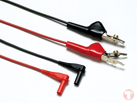
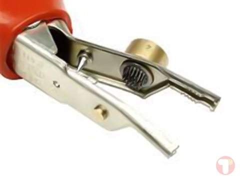
High frequency waveform, meter, capacitance and resistance measurements as well as continuity checks are all covered by single set of shielded test leads. No time is wasted finding or swapping leads.
Fluke Connect mobile app compatibility
Automated industrial machinery is harder than ever to trouble shoot. It’s not enough to just know where you have to test, you also have to know what to look for-and that can be hard without baseline measurement data or access to subject matter experts. The Fluke Connect® Assets wireless system of software and wireless test tools enables technicians to reduce maintenance costs and increase uptime with accurate equipment records and maintenance data that is easy to interpret, and share. Compare and contrast test point measurement data and trends so you can better understand signal characteristics and changes over time. And, by storing maintenance data on the Fluke Cloud™ you can enable team members to access it from wherever and whenever they need to so you can get advice or approvals in the field and get your systems up and running faster than ever before.
Use the comprehensive recorder modes to help find intermittent faults with ease
The toughest faults to find are those that happen only once in a while-intermittent events. They can be caused by bad connections, dust, dirt, corrosion or simply broken wiring or connectors. Other factors, like line outages and sags or the starting and stopping of a motor, can also cause intermittent events resulting in equipment shutdowns. When these events happen, you may not be around to see it. But, your Fluke ScopeMeter® Test Tool will. You can either plot the minimum and maximum peak measurement values or record the waveform trace. And, with expandable micro SD memory, recording sessions can be done for up to 14 days. This recorder is even more powerful with the addition of Recorder Event Detect, which makes detecting and logging intermittent faults easier than ever. Just set a threshold on a meter reading or scope trace and deviations are tagged as unique events. You no longer need to search through masses of data to pinpoint faults, and can quickly step from one tagged event to the next, while still having access to the full data set.
Industrial Bus Health Test verifies electrical signal quality on industrial buses
Bus Health Test analyzes the electrical signals on the industrial bus or network and gives a clear “Good”, “Weak” or “Bad” indication mark for each of the relevant parameters, presented next to the actual measurement value. Measured values are compared to standard values based on the selected bus types (CAN-bus, Profi-bus, Foundation Field, RS-232 and many more), or, unique reference values can be set if different tolerances are required.

