")
")
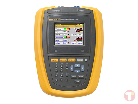
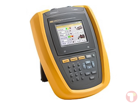
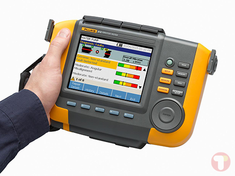
Featuring a portable motor-drive analysis tool that can help to simplify complex motor-drive troubleshooting with guided test setups and automated drive measurements that provide reliable, repeatable test results. It offers basic to advanced measurements, along with a built-in report generator to quickly and easily generate as-found and as-left reports.
Fluke MDA-550 Offers
This motor-drive analyzer saves time and eliminates the hassle of setting up complex measurements, while simplifying the troubleshooting process. Simply select a test and the step-by-step guided measurements show you where to make voltage and current connections, while the preset measurement profiles ensure you will capture all the data you need for each critical motor-drive section—from the input to the output, the DC bus, and the motor itself. From basic to advanced measurements, this tool has you covered, and with a built-in report generator you can quickly and easily generate as-found, and as-left reports with confidence. It is the ideal portable motor-drive analysis test tool, and can help safely locate and troubleshoot typical problems on inverter type motor-drive systems.
Drive Input
Measure input voltage and current to quickly see whether values are within acceptable limits by comparing the drive’s nominal rated voltage to the actual supplied voltage. Then, check the input current to determine if the current is within the maximum rating and the conductors are suitably sized. You can also check whether the harmonic distortion is within an acceptable level by visually inspecting the waveform shape or by viewing the harmonics spectrum screen which shows both the total harmonic distortion and individual harmonics.
Voltage and Current Unbalance
Check the voltage unbalance at the input terminals so you can ensure the phase unbalance is not too high (>6 to 8%), and that the phase rotation is correct. You can also check the current unbalance, as excessive unbalance may indicate a drive rectifier problem.
Extended Harmonic Measurements
Excessive harmonics are not just a threat to your rotating machines but also to other equipment connected to the electrical power system. It provides the ability to discover the harmonics of the motor-drive but can also discover the possible effects of inverter switching electronics. It has three harmonic ranges, 1st to 51st Harmonics, 1 to 9 kHz and 9 to 150 kHz giving the ability to detect any harmonic pollution problems.
DC Bus
In a motor-drive the conversion of AC to DC inside the drive is critical, having the correct voltage and adequate smoothing with low ripple is required for the best drive performance. High ripple voltage may be an indicator of failed capacitors or incorrect sizing of the connected motor. The record function can be used to check DC bus performance dynamically in the operating mode while a load is applied.
Drive Output
Check the output of the drive focusing both on voltage to frequency ratio (V/F), and voltage modulation. When high V/F ratio measurements are experienced, the motor may overheat. With low V/F ratios, the connected motor may not be able to provide the required torque at the load to sufficiently run the intended process.
Voltage Modulation
Measurements of the Pulse Width Modulated signal are used to check for high voltage peaks which can damage motor winding insulation. The rise time or steepness of impulses is indicated by the dV/dt reading (rate of voltage change over time), this should be compared to the motor’s specified insulation. The measurements can also be used to measure switching frequency to identify whether there is a potential issue with electronic switching, or with grounding, where the signal floats up and down.
Motor Input
Ensuring that voltage is being supplied at the motor input terminals is key, and the selection of cabling from drive to the motor is critical. Incorrect cabling selection can result in both drive and motor damage due to excessive reflected voltage peaks. Checking that the current present at the terminals is within the motor rating is important as over current condition could cause the motor to run hot, decreasing the life of the stator insulation which can result in the early failure of the motor.
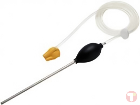
Motor Shaft Voltage
Voltage pulses from a variable speed drive can couple from a motor’s stator to its rotor, causing a voltage to appear on the rotor shaft. When this rotor shaft voltage exceeds the insulating capacity of the bearing grease, flashover currents (sparking) can occur, causing pitting and fluting of the motor bearing race, damage that can cause a motor to fail prematurely. It is supplied with carbon fiber brush probe tips that can easily detect the presence of destructive flashover currents, while the impulse amplitude and count of events will enable you to take action before failure occurs. The addition of this accessory and capability of the MDA-550 allows you to discover potential damage without investing in expensive permanently installed solutions.
Step-by-Step Guided Measurements Ensure You Have the Data You Need, When You Need It
Designed to help you quickly and easily test and troubleshoot typical problems on three-phase and single-phase inverter type motor-drive systems. The on-screen information, and step-by-step setup guidance make it easy to con- figure the analyzer and get the drive measurements you need to make better maintenance decisions, fast. From power input to the installed motor, it provides the measurement capability for the fastest motor-drive troubleshooting.
Reporting and Analysis
Simplifies the process of gathering data and writing test reports with a built-in report generator. At each test point or measurement there is the option to create, update or modify a report. Simply press ‘SAVE TO REPORT’ and select the appropriate screens to save into a text based report file. By performing the step-by-step guided measurements a comprehensive report can be created directly from the instrument to document the entire troubleshooting process. Input the report name. The single report encompasses all recorded measurements and can easily be shared with other users and used for motor- drive benchmarking, and for comparing data now and in the future.
Applications
- Industrial automation
- HVAC/R
- Motor repair
- Discrete or process based industrial manufacturing
- Waste water treatment
- Oil and gas maintenance
What’s included with the Fluke MDA-550
- Motor Drive Analyzer
- 3 x VPS 100:1 High Voltage Probes with Alligator Clips
- VPS410-II-R 10:1 500 MHz Voltage Probe
- 2 x i400s AC Current Clamps
- SVS-500 Shaft Voltage Set
- 3 x Brush
- Probe Holder
- Two-Piece Extension Rod and Magnetic Base
- BC190 Charger/Power Adapter
- 2 GB USB Drive
- FlukeView™ 2 Software
- Manual
- C1740 Carrying Case
- BP 291 Li-Ion Battery Pack